Ring And Pinion Contact Pattern Chart
Dodge Durango Gear Contact Pattern Analysis Adjustments C205f Axle Differential And Driveline
8 2 Gear Pattern Chevy Nova Forum
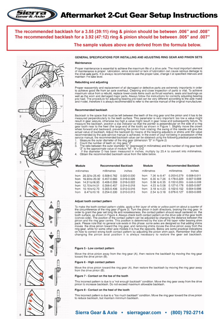
Ring And Pinion Gear Pattern Differential Setup Sierra Gear Axle Sierra Gear Axle Online
New Gears Howling On Deceleration Mustang Forums At Stangnet
Billavista Com Gear Setup Bible Tech Article By Billavista

Winning The Battle Against Axle Noise And Vibration Search Autoparts

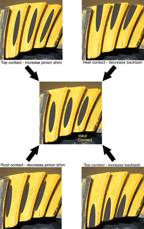
2 cut face hobbed ring and pinion contact pattern summary.
Ring and pinion contact pattern chart.
Two Cut Vs Five Cut Ring Pinion Gears West Coast Differentials
Installing Eaton Trutrac Camaro5 Chevy Camaro Forum Camaro Zl1 Ss And V6 Forums Camaro5 Com

Chrysler 300 300 Touring 300c Dodge Magnum Manual Part 117
Help With 8 8 Rear End Gear Pattern Mustang Forums At Stangnet
Source : pinterest.com
